

Introduction
Modularity in OEM engineering is not a visual preference, a branding decision, or a product-family styling technique. In serious industrial design, modularity is a structured risk-management strategy that allows manufacturers to balance customization, scalability, cost control, manufacturability, serviceability, and long-term field reliability without redesigning the entire system for every application.
Behind most successful industrial product families, there is usually a carefully engineered modular architecture. End users may never notice it directly, because it is often hidden behind external similarity or catalog simplicity, but from the OEM’s perspective it is one of the most important foundations of both engineering discipline and commercial scalability. In drive systems, couplings, gearboxes, interfaces, mounting arrangements, and serviceable subassemblies are often organized in modular layers so that variation can be introduced in controlled places rather than throughout the whole machine.
What “Modular” Really Means in OEM Engineering
In OEM terminology, modularity does not mean that every part can be freely exchanged with every other part. It does not imply arbitrary interchangeability, unlimited flexibility, or unrestricted compatibility. A genuinely modular system is one in which functional boundaries are clearly defined, mechanical and geometric interfaces are standardized, variability is intentionally controlled inside specific modules, and the interaction between those modules remains predictable across the supported configuration range.
Core Drivers Behind Modular Design
OEMs adopt modular strategies because they solve several recurring engineering and business problems at the same time. One of the most important is product line expansion without full re-engineering. Instead of redesigning an entire machine for every torque class, ratio variation, mounting arrangement, or environmental condition, the OEM can preserve a stable core architecture and vary only the modules that need to change.
A second major driver is manufacturing and supply-chain stability. Modular platforms allow shared components to be used across multiple product families, reducing part-count diversity and simplifying inventory planning. This includes the selection of the correct types of couplings to ensure that the mechanical interface remains consistent across diverse drive configurations and service requirements. Such standardization supports parallel supplier qualification and ensures that the core of the drive system remains reliable.
A third driver is application diversity under controlled risk. OEMs serve industries with widely different load spectra, duty cycles, alignment quality, environmental exposure, and installation practices. A modular strategy allows these variations to be accommodated without exposing the entire machine to unknown behavior.
Typical Modular Layers in Drive Systems
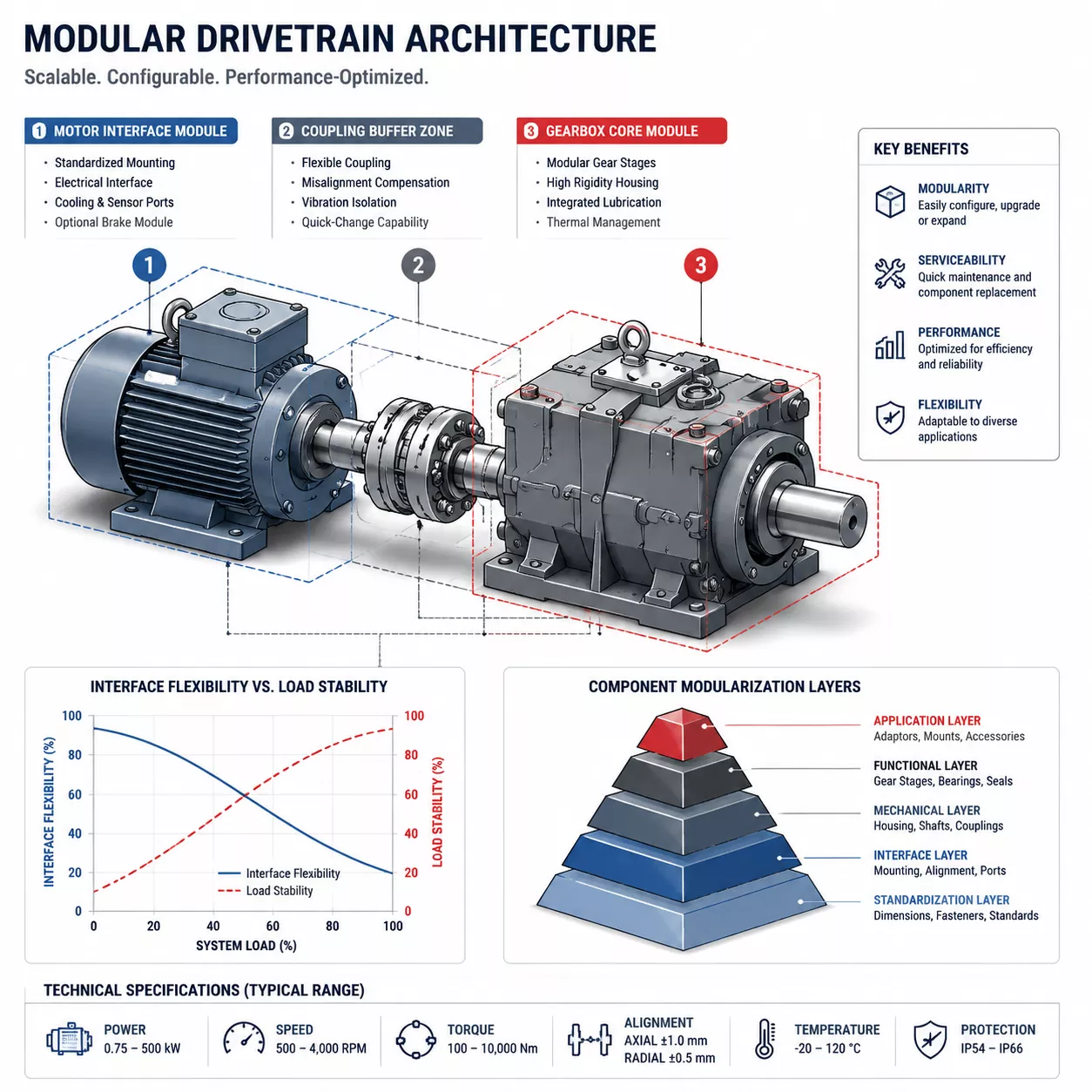
In industrial drive systems, modularity is usually not distributed evenly. OEMs define specific layers where variation is acceptable and protect other areas where stability is more important. One common example is the motor interface module. By isolating motor-side variation in one structured zone, the OEM prevents changes in motor selection from forcing redesign across the rest of the drivetrain.
Another key layer is the coupling module, which functions as a behavioral buffer between subsystems. This is why many engineers evaluate coupling behavior through established manufacturers such as CENTA, KTR, Fenner, VULKAN, REICH, Flender, SEW‑EURODRIVE, NORD DRIVESYSTEMS, and Sumitomo Drive Technologies.
The gearbox core module is usually the least variable part of the architecture. OEMs often protect this zone by stabilizing gear geometry and bearing arrangements. This logic is especially relevant when engineers evaluate industrial gearbox applications by industry or compare architectures through resources such as planetary gearbox vs helical gearbox.
Modular Design vs. Custom Design: The Hidden Trade-Off
Although modularity accelerates development and expands product flexibility, it is never free of compromise. Every module interface introduces additional compliance, geometric tolerance, assembly dependency, and interaction complexity.
Experienced OEMs understand this trade-off very clearly. They do not attempt to modularize everything. In fact, some of the best OEM strategies are defined by knowing where modularity should stop. Critical load paths are often kept monolithic or tightly controlled because introducing too much interface variability in those areas creates unacceptable uncertainty.
Why Modular Failures Often Look Random
One of the recurring problems in the field is that modular systems can fail in ways that appear random to operators or maintenance teams. These events are often failures of interaction. Misalignment, stiffness mismatch, thermal growth, and resonance transfer can all create localized stress concentrations at module interfaces.
For broader product-level reference, one commercial category link is enough, such as industrial rubber couplings, without overloading the article with repeated vendor links.
Modularity and Alignment Chains
Every module added to a drivetrain introduces its own manufacturing tolerance, installation tolerance, and operational deflection. When these are stacked together across a system, they form what can be described as an alignment chain. Mature modular design requires the OEM to understand not just individual tolerances, but how tolerance and deflection propagate across the full assembly.
Mature OEM Strategy: Controlled Modularity
The most capable OEMs practice controlled modularity. This means they modularize interfaces rather than critical load paths, absorb uncertainty as early and as deliberately as possible in the system architecture, and use couplings as tuning elements rather than emergency compensators.
In advanced modular systems, this often leads engineers toward more deliberate comparison between coupling technologies and drivetrain stiffness behavior. Supporting references such as industrial gearbox installation guidelines are useful here, especially when interface behavior is as important as nominal torque capacity.
Implications for Engineers and Integrators
Understanding modular OEM strategy helps engineers interpret catalogs more intelligently. It becomes easier to distinguish between genuine design margin and apparent compatibility. This understanding also improves troubleshooting. When a modular system underperforms, the problem should not automatically be blamed on the failed component, but rather on interface-level issues.
Conclusion
Modular design strategies are not shortcuts. They are disciplined engineering frameworks used by OEMs to control variability, manage uncertainty, and protect long-term reliability. The difference between success and failure lies in how the interactions between those modules are understood, modeled, and controlled.
