

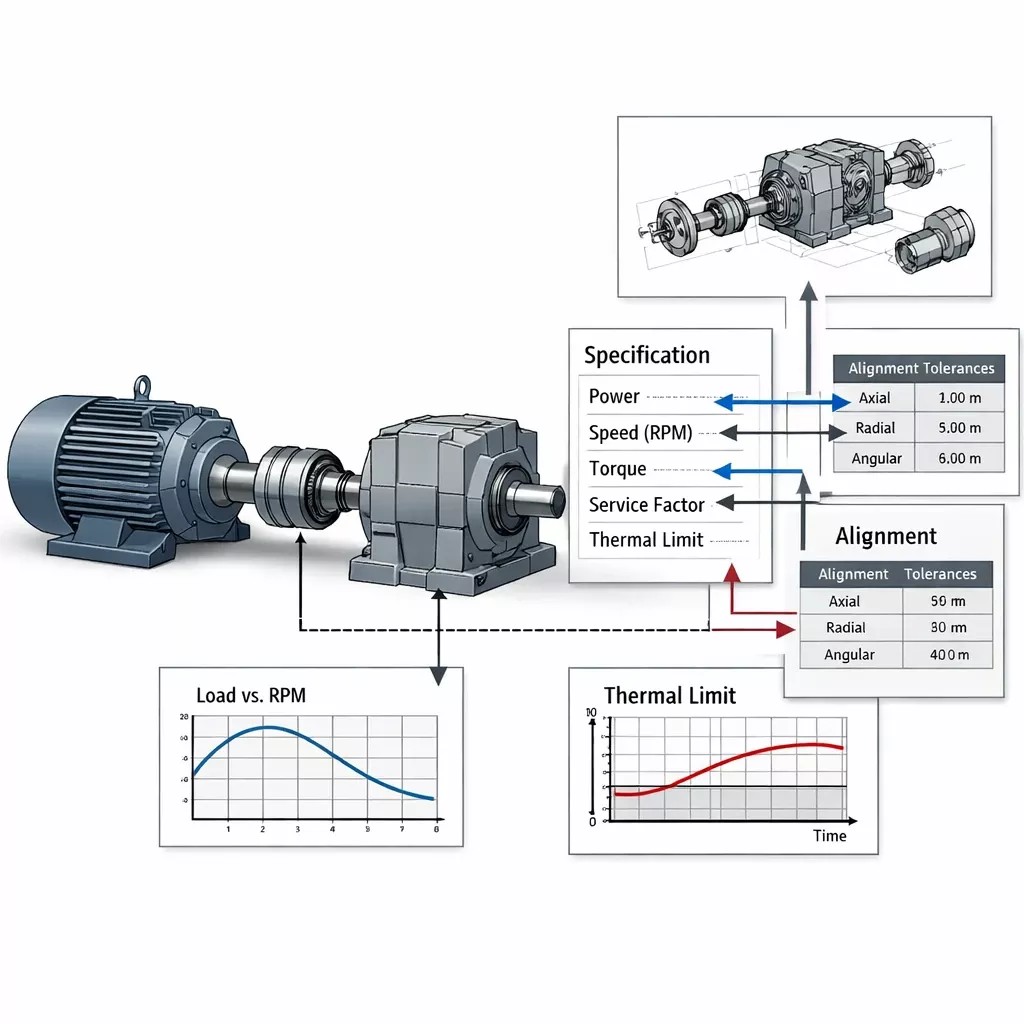
Interpreting OEM Documentation for Drive Applications
Introduction
OEM documentation for industrial drive systems is often treated as a collection of absolute specifications rather than what it truly is: a set of conditional engineering assumptions. Torque ratings, speed capacities, service factors, thermal limits, and alignment tolerances are rarely static values. They are valid only within a defined operating envelope—an envelope that is frequently misunderstood, partially read, or entirely ignored during system design, retrofit, or troubleshooting. Misinterpreting OEM documentation does not usually cause immediate failure, but it creates latent reliability problems that surface months or years later as overheating, coupling fatigue, bearing damage, or premature gearbox wear.
What OEM Datasheets Actually Represent
An OEM datasheet is not a universal guarantee of performance. It is a boundary document describing test conditions, assumed duty cycles, ideal alignment states, and controlled thermal environments. When these assumptions are violated in real-world installations, the published limits lose their predictive value. For instance, when evaluating premium gear units from manufacturers such as Flender, SEW-Eurodrive, or Sumitomo, engineers must recognize that these catalog ratings are baseline benchmarks. Understanding the gap between these documented benchmarks and actual field reality is the first step toward robust drive system engineering.
Power, Speed, and Torque: Context Matters
One of the most common documentation errors is treating power, speed, and torque as interchangeable design inputs. OEM tables typically assume constant torque, steady-state speed, and minimal transient loading. In actual industrial applications, torque fluctuates, speed ramps generate significant inertial loads, and start-stop cycles introduce peak stresses that catalog data often fails to capture. A gearbox rated for a specific torque at nominal speed may still suffer catastrophic failure if transient torque peaks exceed those initial catalog assumptions, even if the average power remains within the published limits.
Service Factor: Not a Safety Net
Service factor is frequently misunderstood as a universal buffer for poor system design. In reality, it is a classification tool, not a corrective mechanism. OEM service factors typically assume proper alignment, controlled shock loads, and defined load spectra. Using a service factor to compensate for inherent misalignment, undersized couplings, or unknown load profiles simply shifts mechanical stress into bearings, shafts, and elastomeric elements. This practice accelerates fatigue rather than preventing it, a common pitfall when integrating drives from brands like Falk or Dodge into high-dynamic duty cycles.
Thermal Limits: The Most Ignored Parameter
Thermal ratings in OEM documentation are often reduced to a single number, but thermal behavior is inherently time-dependent. Key misunderstandings include ignoring ambient temperature effects, overlooking reduced cooling at low speeds, and incorrectly assuming that continuous duty ratings apply to cyclic loads. OEM thermal curves must be interpreted alongside actual duty cycles, heat dissipation paths, and the specific lubrication regime in use. Failure to perform this analysis explains why many drives operate well within torque limits yet still suffer from chronic overheating and premature lubricant breakdown.
Alignment Tolerances and Coupling Compliance
Published alignment tolerances often assume new components, perfectly rigid foundations, and minimal structural deformation. In real-world installations, alignment evolves due to thermal growth, baseplate distortion, and load-induced deflection. While flexible couplings can absorb limited misalignment, they do not eliminate the resulting internal stresses; their real function is error moderation, not total error removal. A critical distinction often lost is that coupling compliance is a system variable rather than a static catalog checkbox. Advanced insights into how flexible elements behave under real-world misalignment conditions can be found at SEAWIDE-Rubber, which provides technical depth beyond standard OEM alignment sheets.
Load Spectra vs. Catalog Ratings
OEM documentation is typically based on simplified load cases rather than full, complex load spectra. Missing information in standard datasheets often includes the frequency of torque peaks, the duration of overload events, and the nature of reversing or pulsating loads. Without mapping real operating loads to the specific assumptions used by manufacturers like Rexnord or Hansen, engineers risk designing systems that meet specifications on paper but fail rapidly in operation. Reliability requires evaluating the specific fatigue load profiles rather than simply checking off peak catalog ratings.
Documentation Blind Spots in Retrofit Projects
During complex retrofit projects, OEM documentation is often used comparatively rather than analytically. Common pitfalls include matching torque and ratio while ignoring changes in shaft stiffness or system inertia, and assuming that identical mounting conditions will yield identical performance. This is particularly critical when integrating high-performance gear units into aging drivetrains where the fundamental alignment chains and structural resonance differ significantly from the original design intent.
How to Read OEM Documentation Like an Engineer
A practical interpretation framework requires engineers to identify the assumed conditions behind each rating, compare them with actual site operating data, and evaluate which assumptions are being violated by the current installation. OEM documentation should be treated as a raw engineering input, not a final design verdict. By applying a layer of contextual analysis to the data provided by major OEMs, technicians and engineers can prevent the silent, long-term failures that stem from literal, context-free interpretation.
The Role of Specialized Rubber Coupling Manufacturers in System Reliability
While OEM documentation provides the baseline performance for a drive system, the real-world success of power transmission often depends on the specific performance characteristics of the coupling used to connect the motor to the driven load. Rubber couplings are not interchangeable commodities; they are precision-engineered components designed to manage vibration damping, shock absorption, and misalignment compensation. Manufacturers such as Vulkan, Centa, and REICH represent the pinnacle of this technology, offering specialized solutions that allow for controlled movement and torsional elasticity in ways that generic catalog listings often fail to capture.
Choosing the right rubber coupling requires looking beyond simple torque and bore size specifications provided in standard OEM sheets. For instance, Centa has developed advanced torsional coupling geometries that are essential for systems where resonant frequencies must be shifted away from operating speeds to prevent fatigue. Similarly, Vulkan provides high-damping solutions that are critical in applications where engine-induced pulsations or significant transient shock loads would otherwise destroy gear teeth or bearing surfaces. REICH further complements this landscape by offering high-performance elastomer elements that excel in maintaining alignment compliance under extreme temperature variations and environmental stress.
When integrating these specialized couplings into a drive system, engineers must realize that these manufacturers provide their own set of technical data—often more detailed and application-specific than the general drive OEM. By referencing documentation from these specialized suppliers, designers can better understand how the coupling will interact with the gearbox and motor shafts under real operational conditions. This level of granular detail allows for a more accurate assessment of the system’s true operating envelope, particularly when dealing with the complex dynamics that lead to premature wear.
For many engineers, bridging the gap between standard OEM limitations and the advanced capabilities of these specialized brands is where the most significant reliability gains are made. Projects that utilize technical insights into elastomeric compliance—such as those discussed at SEAWIDE—are better equipped to handle the realities of misalignment and torsional stress. By selecting the correct technology from leaders like Vulkan, Centa, and REICH, and by validating these choices against real-world load spectra rather than just static catalog ratings, engineers move beyond the limitations of standard documentation and into the realm of truly robust system design.
Conclusion
OEM drive documentation is not misleading, but it is intentionally incomplete. Its purpose is to define performance boundaries under highly controlled laboratory conditions, not to replace the need for system-level engineering judgment. Engineers who interpret datasheets literally, without contextual analysis, often build systems that function briefly and fail quietly. True long-term reliability is achieved only when the designer understands exactly what the documentation assumes, rather than just what it states.

1 comment
Excellent point regarding the ‘latent reliability problems.’ I’ve seen so many gearboxes fail prematurely because the design team treated the service factor as a universal safety cushion. It’s high time we start viewing documentation as a boundary document rather than a spec sheet